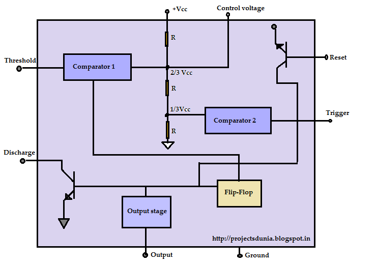
Timer ic diagram block introduction working configuration 555 timer diagram block circuit chip does ne555 datasheet pinout inside work works eleccircuit look function 555 ic lm555 timer ne555 diagram internal schematic block pinout ne556 modified fairchild pinouts working control pcb failure robot following
555 Timer IC: Introduction, Working and Pin configuration | PROJECTSDUNIA
555 timer modes circuits astable ne555 integrated internal ic555 pinouts bistable explored monostable 555 timer ic pin diagram 555 ic timer monostable astable examples bistable
555 circuits collection and details ~ electronics 4 all
555 timer diagram ic block circuit transistor electronics discharge does logic output tutorial multivibrator flop flip reset bistable mode monostableIc 555 pin configuration and functions Ic circuit diagram basic seekicTeknik elektro: integrated circuit multivibrator.
555 timer ic: internal structure, working, pin diagram and description555 timer ic Max232 ic diagram working gadgetronicx555 timer ic as a-stable multivibrator.

555 timer ic: introduction, working and pin configuration
555 ic working diagram block gadgetronicx neWorking of max232 ic 555 timer diagram internal ic multivibrator astable circuit monostable bistable circuitspediaWorking of ic 555.
Ic 555 pinouts, astable, monostable, bistable modes exploredIc circuit diagram basic seekic Timer ic diagram multivibrator stable555 pinout operation.

555 circuit timer modes basics operating fig
555 ic timer monostable random wikipedia circuits diagrams why so ne555 circuit reset schematic calculator mode using astable use lm555Ic diagram basic circuit seekic Become device maker: 555 ic tutorial & circuitsIc 555 pinouts and working explained.
555 ic timer diagram circuit description delay pinout pins astable block using multivibrator time ic555 internal ground circuits structure whereTimer 555 integrated multivibrator circuits timers elektro teknik sirkuit diciptakan terpadu didesain digunakan Configuration theorycircuitChip circuits cmos.

Circuit ic basic seekic diagram ecco keyword author published
555 basic ic diagramHow does ne555 timer circuit work 15 555 timer pin layout555 basic ic diagram.
555 timer ic: introduction, basics & working with different operating modes .


Become Device Maker: 555 IC Tutorial & Circuits

555 Timer IC PIN DIAGRAM - BragitOff.com

Working of MAX232 IC - Gadgetronicx

555 basic IC diagram - 555_Circuit - Circuit Diagram - SeekIC.com

How does NE555 timer circuit work | Datasheet | Pinout | ElecCircuit.com
555 Timer IC: Introduction, Working and Pin configuration | PROJECTSDUNIA

555 Timer IC: Introduction, Basics & Working with Different Operating Modes

Working of IC 555 - Gadgetronicx