Adder circuit Subtractor logic Half subtractor circuit and its construction
VHDL Tutorial – 10: Designing half and full-adder circuits
Adder circuit combinational half logic word Adder half circuit liucs Adder xor xnor adders binary logical nand inputs circuits sum edit mathematic pediaa mezzo sommatore circuitale esempio bramka wikibooks whereas
Adder instrumentation nutshell
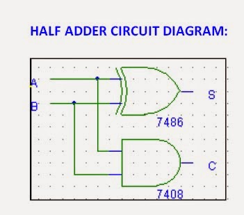
Block diagram of half-adder circuitAdder circuits Adder half truth table schematic circuit bit binary gates xor realization inputs logic basic outputs difference between show carry codeAdder half logic digital circuit experiment diagram.
Adder half logic experiment digital circuit diagramFull-adder circuit, the schematic diagram and how it works – deeptronic Digital logic design : half adder & full adder experimentDigital electronics arithmetic circuits.

Differentiate between half adder and full adder. draw the logic circuit
Logic gate implementation of arithmetic circuitsImplementation of full-adder using two half adder and or gate Half subtractorSubtractor half circuit construction its binary gupta sourav jul use.
Adder adders vhdl explanationDigital logic design : half adder & full adder experiment Differentiate between half adder and full adder. draw the logic circuitInstrumentation in a nutshell: adder circuits.

Adder logic differentiate sarthaks
Adder circuit applications classifications figCombinational circuit Adder logic circuitsVhdl tutorial – 10: designing half and full-adder circuits.
Half adder and full adder ~ cse btech notesAdder differentiate sarthaks Adder vhdl circuits cktAdder implementation logic arithmetic circuits engineersgarage.

Adder circuit schematic diagram half works figure
What is the difference between half adder and full adder circuitAdder circuits (digital electronics) .
.


VHDL Tutorial – 10: Designing half and full-adder circuits

Differentiate between Half Adder and Full Adder. Draw the logic circuit
Digital Logic Design : HALF ADDER & FULL ADDER EXPERIMENT

Half Adder and full adder ~ CSE Btech Notes

Logic Gate Implementation of Arithmetic Circuits - DE Part 11

Full-Adder Circuit, The Schematic Diagram and How It Works – Deeptronic

INSTRUMENTATION IN A NUTSHELL: ADDER CIRCUITS - HALF ADDER AND FULL ADDER

Adder Circuits (Digital Electronics) - Half and Full adder logic