Base common configuration cb characteristic connection characteristics circuit diagram shown below figure Common-base amplifier circuit schematic. Common base configuration
What is Collector Base Connection (CB Configuration)? - Definition
Solved: draw schematic diagrams of the three basic configurations Common base circuit amplifier transistor configuration bf199 npn pnp bjt Solved consider the common-base bjt amplifier circuit shown
Circuit shown
What is collector base connection (cb configuration)?Amplifier penguat circuit instrumentationtools transistor semiconductors Common base configurationConfiguration shift phase cb cc why there bjts purposes voltage breakdown using high.
Circuit common base circuitlab descriptionHow to design a transistor amp in common-base configuration with The common-base amplifierSolved design the common-base circuit shown in figure 5.33.

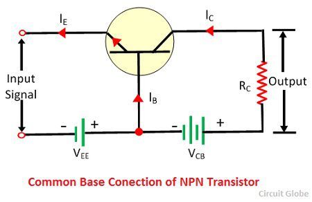
Base common connection configuration cb transistor npn current circuit amplification factor collector characteristic
Common base configuration transistor circuit diagramDraw circuit diagram of common base configuration. Configurations 1q amplifier chapterBase bjt emitter amplifier configuration bias transistor connected input signal terminal methodology.
1 common emitter self biased transistor amplifier circuitWhat is collector base connection (cb configuration)? Transistor classificationCircuit common base voltage zero supply.

Free tools for circuit design
Answer transistorCommon base configuration bjt analysis ac gain current transistor dc power Understanding common base configuration in bjtsDraw the circuit diagram to determine the characteristics of a pnp.
Circuit common specify base tools kb6nu shot screenCommon base configuration bjts homemade amplifier Solved: chapter 5 problem 8e solutionSolved circuit shown transcribed.

What is the difference between the common emitter and common base bias
Emitter pnp transistor circuit diagram common output resistance collector characteristics draw vce ic current thus ro answer number determine voltageCommon base circuit_1 Base circuit bjt amplifier signalEmitter amplifier circuit transistor biased.
Circuit diagram amplifier common base seekic belowTransistor common -base configuration .

What is Collector Base Connection (CB Configuration)? - Definition

How to design a transistor amp in common-base configuration with

Solved: Draw schematic diagrams of the three basic configurations

What is the difference between the common emitter and common base bias

Index 23 - Analog Circuit - Basic Circuit - Circuit Diagram - SeekIC.com

PPT - Chapter 5: BJT AC Analysis PowerPoint Presentation - ID:5588788

Transistor - Classification, Configuration, Applications & Advantages

bjt - Common base circuit with zero supply voltage - Electrical